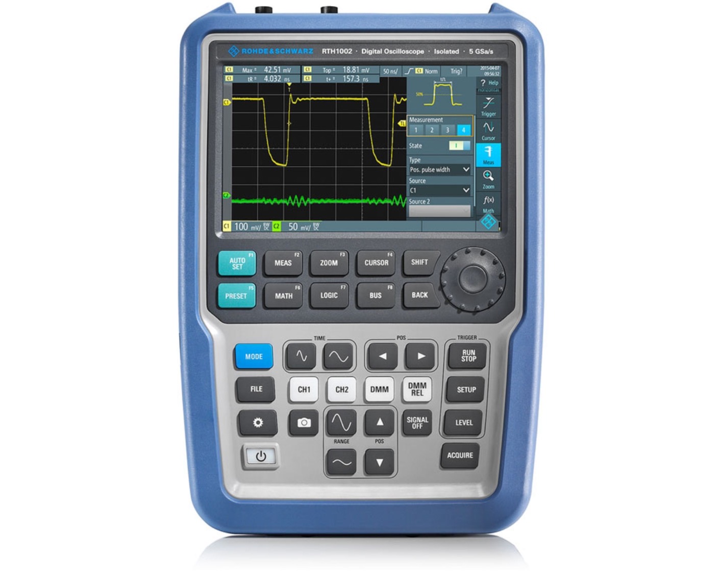
Программная опция Rohde & Schwarz RTH-B1
| Номер в Госреестре | Наименование СИ | Обозначение типа СИ | Изготовитель | Срок свидетельства или заводской номер |
|---|---|---|---|---|
| не в реестре | ||||
Vertical system
| Input channels | 8 logic channels (from D0 to D7) | |
| Input impedance | 100 kΩ ± 2 % || ~4 pF (meas.) at probe tips | |
| Maximum input frequency | signal with minimum input voltage swing and hysteresis setting: normal | 250 MHz (meas.) |
| Maximum input voltage | ±40 V (peak) | |
| Minimum input voltage swing | 500 mV (peak-to-peak) (meas.) | |
| Threshold groups | from D0 to D3, D4 to D7 | |
| Threshold level | range | ±8 V in 25 mV steps |
| predefined | CMOS 5.0 V, CMOS 3.3 V, CMOS 2.5 V, TTL, ECL, PECL, LVPECL | |
| Threshold accuracy | ±(100 mV + 3 % of threshold setting) | |
| Comparator hysteresis | normal, robust, maximum |
Horizontal system
| Channel deskew | range for each channel | ±100 ns |
| Channel-to-channel skew | < 2 ns (meas.) |
Acquisition system
| Maximum realtime sampling rate | 1.25 Gsample/s on each channel |
| Maximum acquisition length for fast time bases (less than or equal to 20 ms/div) | 125 ksample for each channel |
| Maximum acquisition length for slow time bases (greater than or equal to 50 ms/div) | 125 ksample for each channel (sampleacquisition mode of analog channels even if no analog channel is active) |
| 62.5 ksample for each channel (high resolution, peak detect, envelope and average acquisition modes of analog channels even if no analog channel isactive) |
Trigger system
| Trigger level | range | ±4 div from center of screen |
| Trigger modes | auto, normal, single | |
| Trigger sources | R&S®RTH1004 | logic channels from D0 to D7CH1, CH2, CH3, CH4 |
| R&S®RTH1002 | logic channels from D0 to D7CH1, CH2 | |
| Hold off range | time | 8 ns to 10 s, fixed and random |
| events | 1 to 1 000 000 000 events |
| Trigger types | ||
| Edge | triggers on specified slope (positive, negative or either) and level | |
| Glitch | triggers on glitches of positive, negative or either polaritiy that are shorter or longer than specified width | |
| glitch width | 800 ps to 5000 s (CH1, CH2, CH3, CH4) | |
| 800 ps to 5000 s (D0 to D7) | ||
| Width | triggers on positive or negative pulse of specified width; width can be shorter, longer,inside or outside the interval | |
| pulse width | 800 ps to 5000 s (CH1, CH2, CH3, CH4) | |
| 800 ps to 5000 s (D0 to D7) | ||
| Pattern | triggers when a logical combination (and, nand, or, nor) of the input channels stays true for a period of time shorter, longer, inside or outside a specified range(requires R&S®RTH-K19 option) | |
| pattern time | 800 ps to 5000 s (CH1, CH2, CH3, CH4) | |
| 800 ps to 5000 s (D0 to D7) | ||
| State | triggers when a logical combination (and, nand, or, nor) of the input channels stays true at a slope (positive, negative or either) in one selected channel; state values may be high (H), low (L) or don’t care (X) (requires R&S®RTH-K19 option) | |
| Data2clock | triggers on setup time and hold time violations between clock and data present on any two input channels; monitored time interval may be specified by the user with a step size of 800 ps in the range from –124 ns to 124 ns around a clock edge(requires R&S®RTH-K19 option) | |
| Serial pattern | triggers on serial data pattern up to 32 bit clocked by one input channel; pattern bitsmay be high (H), low (L) or don’t care (X); clock edge slope may be positive, negative or either (requires R&S®RTH-K19 option) | |
| max. data rate | < 250 Mbps | |
| Timeout | triggers when signal stays high, low or unchanged for a specified period of time (requires R&S®RTH-K19 option) | |
| timeout | 800 ps to 5000 s (CH1, CH2, CH3, CH4) | |
| 800 ps to 5000 s (D0 to D7) | ||
| Interval | triggers when time between two consecutive edges of same slope (positive or negative) is shorter, longer inside or outside a specified range(requires R&S®RTH-K19 option) | |
| interval time | 800 ps to 5000 s (CH1, CH2, CH3, CH4) | |
| 800 ps to 5000 s (D0 to D7) | ||
| Protocol | see R&S®RTH-K1, R&S®RTH-K2, R&S®RTH-K3, R&S®RTH-K9 and R&S®RTH-K10options | |
Waveform measurements
| Automatic measurements on | total number of active measurements | 4 |
| sources | logic channels from D0 to D7 | |
| time based measurements | period, frequency, positive pulse width, negative pulse width, positive duty cycle,negative duty cycle, delay, phase | |
| amplitude based measurements | mean value | |
| count based measurements | count positive pulses, count negativepulses, count rising edges, count falling edges | |
| Cursor measurements | sources | logic channels from D0 to D7 |
| vertical | 2 cursors showing time, time difference and inverse time difference (frequency) | |
| tracking | vertical cursor additionally showing logic level and logic level difference of selected channel | |
| measure | defines gate for automatic measurements |
Подробные технические характеристики, информация производителя, брошюры:
-
-
 Каталог продукции Rohde and Schwarz 2019 RUS.pdf
Каталоги производителя:
-
