с полосой пропускания 1 ГГц, 4 канала
Стоимость указана в Рублях DDP Москва по безналичному расчету включая НДС 20%


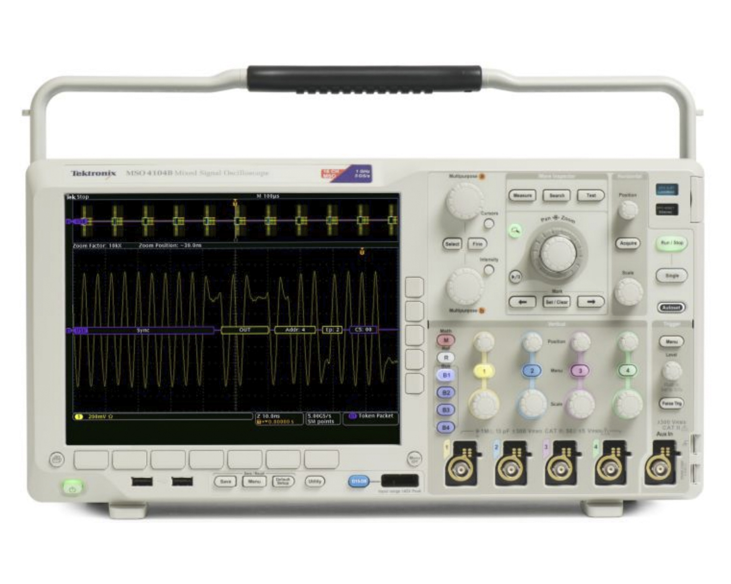
Цифровой осциллограф Tektronix TDS7104
с полосой пропускания 1 ГГц, 4 канала
Стоимость указана в Рублях DDP Москва по безналичному расчету включая НДС 20%
TDS7104
По запросу
включая НДС
Запросить счетЦифровые осциллографы серии TDS7000 обеспечивают лучшее в отрасли решение сложных проблем целостности сигнала, с которыми сталкиваются разработчики, проверяющие, характеризующие и отлаживающие сложные электронные конструкции. Семейство отличается исключительным сбором и анализом сигналов, простотой в эксплуатации и полным подключением к вашей среде проектирования и стороннему программному обеспечению для анализа.
- Время нарастания 400 пс
- Полоса пропускания 1 ГГц
- Частота дискретизации в реальном времени 10 GS/s
- Глубина памяти до 16 Мегабайт
- >200 000 Wfms/сек максимальная скорость захвата формы сигнала
- Исключительная точность дельта-времени для высокой достоверности измерений критического времени
- Тестирование маски связи со скоростью до 2,5 Гбит/с
- Восстановление тактовой частоты из последовательных потоков данных
- 32-разрядный последовательный триггер для выделения эффектов, зависящих от шаблона
- Опорный вход временной базы 10 МГц для повышения точности и повторяемости
- Многовидовое масштабирование для быстрой навигации по длинным записям
- Управление с помощью классического прямого управления, сенсорного цветного дисплея или навигации с помощью мыши
Комплектация
- Option 3M — Long record length: 4 Msamples per channel, 16 Msamples maximum
- Option SM — Serial Communications Mast Testing
- Option J2 — TDSDDM2 Disk Drive Measurements application
- Option J1 — TDSJIT2 Jitter Analysis application
- Option USB — TDSUSBS--USB2.0 Compliance Test application (Software only)
- TDSCPM2 — Communications Pulse Measurement Software
- TDSDVD — Optical Storage Analysis and Measurement Software
- Option JT3 — TDSJIT3 Advanced Jitter Analysis application with random and deterministic jitter analysis
- Option RTE – RT-Eye® Serial Data Compliance and Analysis Software
- Opt. PCE – PCI Express™ Compliance Module for RT-Eye Serial Data Compliance and Analysis Software
- TDSJIT3 Essentials — Jitter and Timing Analysis Software
- TDSPWR3 — Power Measurement and Analysis Software
- TDSET3 — Ethernet Compliance Test Software
| Номер в Госреестре | Наименование СИ | Обозначение типа СИ | Изготовитель | Срок свидетельства или заводской номер |
|---|---|---|---|---|
| 28769-05 | Осциллографы цифровые | TDS7704B, TDS7054, TDS7104, TDS7154B, TDS7254B, TDS7404B, CSA7404B, CSA7154 | Компания "Tektronix, Inc.", США | 01.03.2010 |
Vertical System
| Input Channels | 4 |
| Analog Bandwidth (–3 dB) | 1 GHz |
| Calculated Rise Time 10 mV/div to 1 V/div | 400 ps |
| Hardware Bandwidth Limits | 250 MHz or 20 MHz |
| Input Coupling | AC, DC, Gnd |
| Input Impedance | 1 MΩ ±0.5% or 50 Ω ±1% |
| Input Sensitivity, 1 MΩ | 1 mV/div to 10 V/div |
| Input Sensitivity, 50Ω | 1 mV/div to 1 V/div |
| Vertical Resolution | 8-Bit (>11-Bit with averaging) |
| Max Input Voltage, 1 MΩ | ±150 V CAT I Derate at 20 dB/decade to 9 VRMS above 200 kHz |
| Max Input Voltage, 50Ω | 5 VRMS, with peaks less than ±30 Volts |
| DC Gain Accuracy | 1% |
| Offset Range | |
| 1 mV/div to 100 mV/div: ±1 V | |
| 101 mV/div to 1 V/div: ±10 V | |
| 1.01 V/div to 10 V/div: ±100 V | |
| Channel-to-channel Isolation Any Two Channels at Equal Vertical Scale Settings | ≥100:1 at 100 MHz and ≥30:1 at the Rated Bandwidth |
Time Base System
| Time Base Range | 200 ps/div to 40 s/div |
| Time Base Delay Time Range | 16 ns to 250 s |
| Channel-to-channel Deskew Range | ±25 ns |
| Delta Time Measurement Accuracy | ±((0.06/sample rate) + (15 ppm * reading)) RMS |
| Trigger Jitter (RMS) | 8 psRMS (typical) 6 psRMS (typical) |
| Long Term Sample Rate and Delay Time Accuracy | ±15 ppm over ≥1 ms interval |
Acquisition System
| Real-time Sample Rates | TDS7104 |
|---|---|
| 1 channel (max) | 10 GS/s |
| 2 channels (max) | 5 GS/s |
| 3 to 4 channels (max) | 2.5 GS/s |
| Equivalent Time Sample Rate (max) | 250 GS/s |
| Maximum Record Length per Channel with Standard Memory | 2 M (1-CH.), 1 M (2-CH.), 500 k (4-CH.) |
| with Memory Opt. 2M | 8 M (1-CH.), 4 M (2-CH.), 2 M (4-CH.) |
| with Memory Opt. 3M | 16 M (1-CH.), 8 M (2-CH.), 4 M (4-CH.) |
Maximum Duration at Highest Real-time Resolution (1-CH)
| Time Resolution (Single-shot) | 100 ps (10 GS/s) |
| Max Duration with Standard Memory | 200 μs |
| Max Duration with Opt. 2M | 800 μs |
| Max Duration with Opt. 3M | 1.6 ms |
Acquisition Modes
| FastAcq Acquisition | FastAcq optimizes the instrument for analysis of dynamic signals and capture of infrequent events |
| Maximum FastAcq Waveform Capture Rate | >200,000 wfms/sec |
| Waveform Database (requires Option SM) | Accumulate Waveform Database providing three-dimensional array of amplitude, time and counts |
| Sample | Acquire sampled values |
| Peak Detect | Captures narrow glitches at all real-time sampling rates |
| Minimum Peak Detect Pulse Width | ≤1 ns |
| Averaging | From 2 to 10,000 waveforms included in average |
| Envelope | From 2 to 2x10⁹ waveforms included in min-max envelope |
| Hi-res | Real-time boxcar averaging reduces random noise and increases resolution |
| FastFrame™ Acquisition | Acquisition memory divided into segments; maximum trigger rate >160,000 waveforms per second. Time of arrival recorded with each event |
Trigger System
| Sensitivity | |
| Internal DC Coupled | 0.35 div DC to 50 MHz increasing to 1 div at 1 GHz |
| External (Auxiliary Input) | 250mV from DC to 50 MHz increasing to 500mV at 100 MHz |
| Main Trigger Modes | Auto, Normal and Single |
| Trigger Sequences | Main, Delayed by Time, Delayed by Events. All sequences can include separate horizontal delay after the trigger event to position the acquisition window in time |
| Trigger Characteristics | |
| Standard Trigger Types | Edge, Glitch, Runt, Width, Transition Time, Timeout, Pattern, State, Setup/Hold |
| Communications-related | Support for AMI, HDB3, BnZS, CMI, MLT3 and NRZ encoded communications signals. |
| Triggers (requires Option SM) | Select among isolated positive or negative one, zero pulse form or eye patterns as applicable to standard. |
| Trigger Level Range | |
| Internal | ±12 divisions from center of screen |
| External (Auxiliary In) | ±8 V |
| Line | fixed at 0 V |
| Trigger Coupling | DC, AC (attenuates <60 Hz), HF Rej (attenuates >30 kHz), LF Rej (attenuates <80 kHz), Noise Reject (reduces sensitivity) |
| Trigger Holdoff Range | 250 ns minimum to 12 s maximum |
Trigger Modes
| Edge | Positive or negative slope on any channel or front panel auxiliary input. Coupling includes DC, AC, noise reject, HF reject and LF reject. |
| Glitch | Trigger on or reject glitches of positive, negative or either polarity. Minimum glitch width is 1.0 ns with 200 ps resolution. |
| Width | Trigger on width of positive or negative pulse either within or out of selectable time limits (1 ns to 1 s). |
| Runt | Trigger on a pulse that crosses one threshold but fails to cross a second threshold before crossing the first again. Optional time qualification. |
| Timeout | Trigger on an event which remains high, low or either, for a specified time period, selectable from 1 ns to 1 s with 200 ps resolution. |
| Transition | Trigger on pulse edge rates that are faster or slower than specified. Slope may be positive, negative or either. |
| Setup/Hold | Trigger on violations of both setup time and hold time between clock and data present on any two input channels. |
| Pattern | Trigger when pattern goes false or stays true for specified period of time. Pattern (AND, OR, NAND, NOR) specified for four input channels defined as HIGH, LOW or Don’t Care. |
| State | Any logical pattern of channels (1, 2, 3) clocked by edge on channel 4. Trigger on rising or falling clock edge. |
| Trigger Delay by Time | 16 ns to 250 seconds. |
| Trigger Delay by Events | 1 to 10,000,000 Events. |
Waveform Measurements
| Amplitude | Amplitude, High, Low, Maximum, Minimum, Peak to Peak, Mean, Cycle Mean, RMS, Cycle RMS, Positive Overshoot, Negative Overshoot. |
| Time | Rise time, Fall time, Positive Width, Negative Width, Positive Duty Cycle, Negative Duty Cycle, Period, Frequency, Delay. |
| Combination | Area, Cycle Area, Phase, Burst Width. |
| Histogram-related | Waveform count, Hits in box, Peak hits, Median, Maximum, Minimum, Peak to Peak, Mean (μ), Standard Deviation (σ), μ+1σ, μ+2σ, μ+3σ. |
Waveform Processing/Math
| Algebraic Expressions | Define extensive algebraic expressions including waveforms, scalars and results of parametric measurements e.g. (Integral (CH.1-Mean(CH.1))*1.414). |
| Arithmetic | Add, subtract, multiply, divide waveforms and scalars. |
| Relational | Boolean result of comparison >, <, >=, <=, ==, !=. |
| Calculus | Integrate, differentiate. |
| Frequency Domain Functions | Spectral magnitude and phase, real and imaginary spectra. |
| Vertical Units | Magnitude: Linear, dB, dBm; Phase: Degrees, radians. |
| Window Functions | Rectangular, Hamming, Hanning, Kaiser-Bessel, Blackman-Harris, Gaussian, Flattop2, Tek Exponential. |
| Waveform Definition | As arbitrary math expression. |
Подробные технические характеристики, информация производителя, брошюры:
-
-
 Tektronix Каталог продукции 2019.pdf
Каталоги производителя:
-