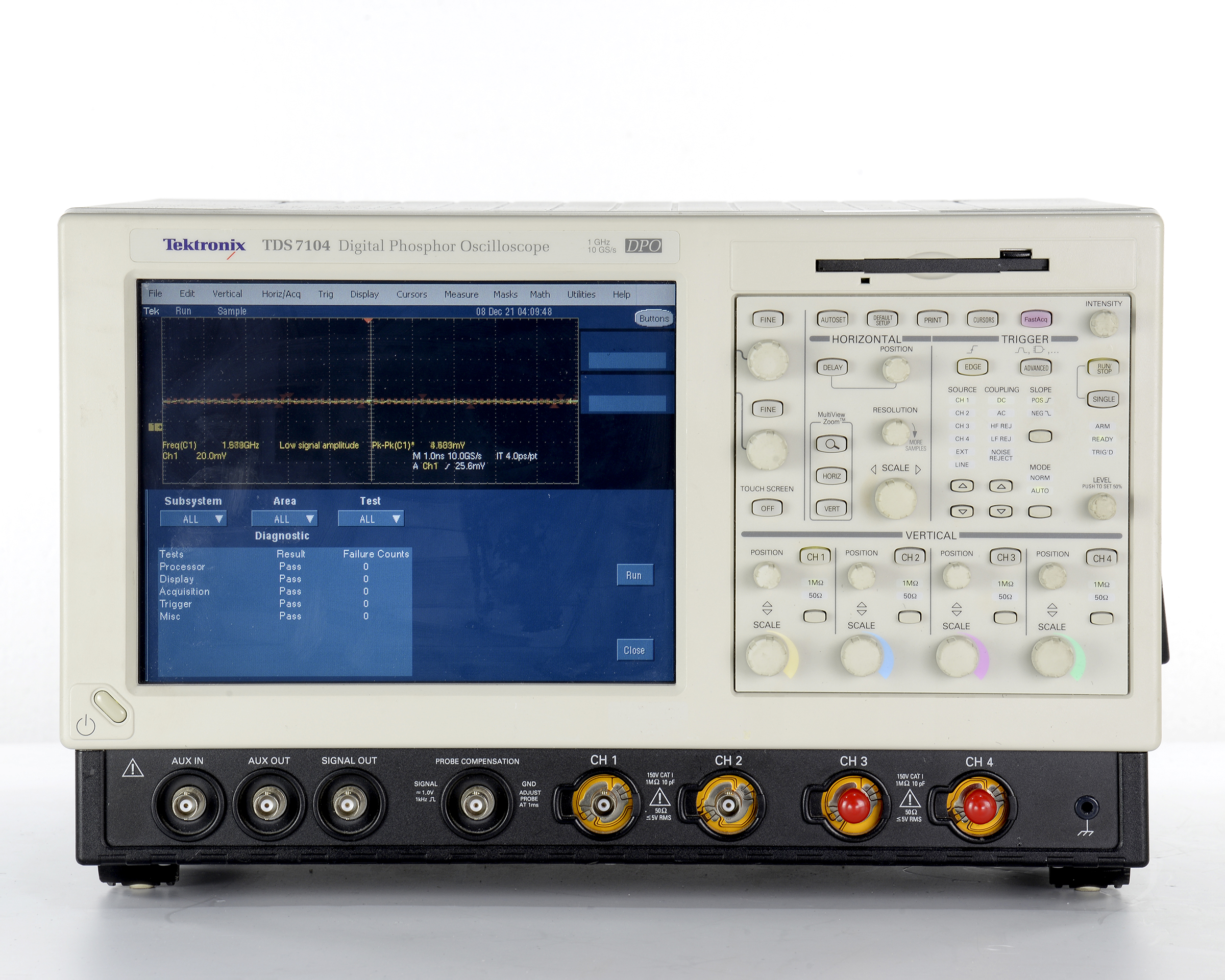
Tektronix TDS5054B-NV-T
с полосой пропускания 500 МГц, 4 канала
Стоимость указана в Рублях DDP Москва по безналичному расчету включая НДС 20%


Цифровой осциллограф
Tektronix TDS5054B-NV-T
с полосой пропускания 500 МГц, 4 канала
Стоимость указана в Рублях DDP Москва по безналичному расчету включая НДС 20%
TDS5054B-NV-T
285 000 руб.
включая НДС
Запросить счетОсциллографы с цифровым люминофором TDS5000B (DPO) обеспечивают полосу пропускания 350 МГц, 500 МГц или 1 ГГц, частоту дискретизации 5 Гвыб/с в реальном времени, длину записи до 16 млн и набор расширенных триггеров, что позволяет захватывать и характеризовать даже ваши самые требовательные сигналы. DPO обеспечивают непревзойденное понимание поведения сигнала, отображая, сохраняя и анализируя сложные сигналы в режиме реального времени с использованием трех измерений информации о сигнале: амплитуды, времени и распределения амплитуды во времени. Модели TDS5000B DPO с собственной технологией сбора данных Tektronix DPX® обеспечивают скорость захвата более 100 000 осциллограмм в секунду. Некоторые поставщики осциллографов заявляют о высокой скорости захвата сигналов в течение коротких промежутков времени, но только DPO, оснащенные технологией DPX, могут обеспечивать такую высокую скорость захвата сигналов на постоянной основе, экономя минуты, часы или даже дни за счет быстрого выявления характера неисправностей. поэтому для их изоляции можно применять сложные режимы запуска. Модели TDS5000B включают полную систему параметрических измерений для характеристики сигнала. Выберите из 53 автоматических измерений, используя графическую палитру, которая логически организует измерения по категориям «Амплитуда», «Время», «Комбинация», «Гистограмма» и «Связь». Соберите дополнительные сведения о результатах измерений с помощью статистических данных, таких как среднее, минимальное, максимальное значение, стандартное отклонение и совокупность. Курсоры осциллограмм упрощают измерение временных характеристик от трассы к трассе, а курсоры, связывающие режимы отображения YT и XY, упрощают исследование фазовых соотношений и нарушений безопасной рабочей области. Определите и примените математические выражения к данным сигнала для отображения результатов на экране в терминах, которые вы можете использовать. Доступ к стандартным математическим функциям сигналов одним нажатием кнопки. Или, для расширенных приложений, создавайте алгебраические выражения, состоящие из источников сигналов, математических функций, значений измерений, скаляров и настраиваемых пользователем переменных с помощью простого в использовании редактора в стиле калькулятора. Для расширения возможностей TDS5000B можно установить расширения прикладных измерений. Эти программные приложения основаны на высокоточных характеристиках серии TDS5000B и удовлетворяют потребность в измерениях для конкретных приложений для быстрой количественной оценки производительности устройств и систем. Дополнительные приложения включают в себя измерение и анализ мощности, анализ джиттера и временных характеристик, измерения дисковых накопителей, соответствие телекоммуникационным импульсам ANSI/ITU и тестирование на соответствие стандарту Ethernet.
Особенности и преимущества:
- Полоса пропускания 500 МГц (TDS5054B)
- 4 канала
- Частота дискретизации до 5 Гвыб/с
- Длина записи до 16 млн.
- 100 000 осц/с Максимальная скорость захвата сигнала
- MyScope™ Custom Control Windows Повышение производительности
- Меню правой кнопкой мыши для исключительной эффективности
- Платформа OpenChoice® с Windows 2000 обеспечивает встроенную сеть и анализ
- Небольшой размер / легкий вес
- 10,4-дюймовый яркий дисплей
- Стандартный сенсорный экран
- Набор расширенных триггеров
- Тестирование маски связи
- Пройдено/не пройдено предельные испытания
- Удаленный просмотр и управление
- Электронная почта о событии
- CD-RW дисковод
- Совместимость с логическими анализаторами Tektronix
- Контроллер GPIB
Комплектация
В комплекте с опциями:
- Опция 3M — Расширение памяти до макс. 16 мил. точек (Long record length: 4 Msamples per channel, 16 Msamples maximum)
- Опция SM — Тестирование коммуникационных сигналов по маске (Serial Communications Mast Testing)
- Опция ST — Serial Pattern Triggering
- Опция J2 — TDSDDM2 – ПО для измерений параметров приводов дисков (TDSDDM2 Disk Drive Measurements application)
- Опция USB — ПО для проверки на совместимость с USB 2.0 (USB 2.0 Test Package)
- Опция PW3 — TDSPWR3 – ПО для измерений мощности (TDSPWR3 – Power measurement software)
- Опция ET3 — TDSET3 – ПО для проверки на соответствие с Ethernet (TDSET3 – Ethernet compliance test software)
- Опция CP2 — TDSCPM2 - ПО для проверки на соответствие коммуникационным сигналам ANSI/ITU (TDSCPM2 – ANSI/ITU telecom pulse compliance testing software)
- TDSRG — Report Generator
| Номер в Госреестре | Наименование СИ | Обозначение типа СИ | Изготовитель | Срок свидетельства или заводской номер |
|---|---|---|---|---|
| 28768-10 | Осциллографы цифровые | TDS5104B, TDS5032B, TDS5034B, TDS5052B, TDS5054B, TDS5054BE | Компания "Tektronix, Inc.", США | 01.04.2015 |
| 28768-05 | Осциллографы цифровые | TDS5104B, TDS5032B, TDS5034B, TDS5052B, TDS5054B, TDS5054BE | Компания "Tektronix, Inc.", США | 01.03.2010 |
| Vertical System | |
|---|---|
| Characteristic | TDS5054B |
| Input Channels | 4 |
| Analog Bandwidth (–3 dB) 5 mV/div - 1 V/div | 500 MHz |
| Calculated Rise Time 5 mV/div (Typical) | 800 ps |
| Hardware Bandwidth Limits | 150 MHz or 20 MHz |
| Input Coupling | AC, DC, GND |
| Input Impedance, 1 MΩ | ±1% |
| Input Impedance, 50 Ω | ±1% |
| Input Sensitivity, 1 MΩ | 1 mV/div to 10 V/div |
| Input Sensitivity, 50 Ω | 1 mV/div to 1 V/div |
| Vertical Resolution | 8 bits (>11 bits w/ averaging) |
| Max Input Voltage, 1 MΩ | 150 V CAT I, ≤400 V peak. Derate at 20 dB/decade to 9 VRMS above 200 kHz |
| Max Input Voltage, 50 Ω | 5 V RMS with peaks < ±30 V |
| DC Gain Accuracy | 1.5% with offset set to 0 V |
| Offset Range, 1 MΩ | 1 mV/div - 99.5 mV/div ±1 V 100 mV/div - 1 V/div ±10 V 1.01 V/div - 10 V/div ±100 V |
| Offset Range, 50 Ω | 1 mV/div - 99.5 mV/div ±1 V 100 mV/div - 1 V/div ±10 V |
| Channel-to-Channel Isolation for Any Two Channels at Equal Vertical Scale | ≥100:1 at ≤100 MHz and ≥30:1 at >100 MHz up to the rated bandwidth |
| Time-base System | |
| Characteristic | Description |
| Time-base Range | 200 ps/div to 1000 s/div |
| Time-base Delay Time Range | (s/div × 10) to 1000 s |
| Channel-to-Channel Deskew Range | ±75 ns |
| Time-base Accuracy | 15 ppm |
| Delta Time Measurement Accuracy | (0.06/sample rate + 15 ppm × |Reading|) RMS |
| Trigger Jitter (RMS) | 8 psRMS (typical) |
| Long-term Sample Rate and Delay Time Accuracy | ±15 ppm over any ≥1 ms interval |
| Acquisition System | |
| Characteristic | TDS5054B |
| Real-time Sample Rates | |
| 1 Channel (Max) | 5 GS/s |
| 2 Channels (Max) | 2.5 GS/s |
| 3-4 Channels (Max) | 1.25 GS/s |
| Equivalent Time Sample Rate (Max) | 250 GS/s |
| Maximum Record Length per Channel with Standard Memory | 16M/8M/4M |
| With Opt. 3M | NA |
| Maximum Duration at Highest Real-time Resolution (1 ch) | |
| Characteristic | TDS5054B |
| Time Resolution (Single shot) | 200 ps (5 GS/s) |
| Max Duration with Standard Memory | 3.2 ms |
| Max Duration with Opt. 3M | NA |
| Acquisition Modes | |
| Characteristic | Description |
| FastAcq Acquisition | FastAcq optimizes the instrument for analysis of dynamic signals and capture of infrequent events. Maximum FastAcq waveform capture rate is 100,000 wfms/s |
| Sample | Acquire sampled values |
| Peak Detect | Captures narrow glitches (<1 ns) at all real-time sampling rates |
| Averaging | From 2 to 10,000 waveforms included in average |
| Envelope | From 2 to 20,000,000 waveforms included in min-max envelope |
| Hi-Res | Real-time boxcar averaging reduces random noise and increases resolution |
| Waveform Database | Accumulates a waveform database that provides a three-dimensional array of amplitude, time, and counts |
| FastFrame™ Acquisition | Acquisition memory divided into segments; maximum trigger rate >100,000 waveforms per second |
| Trigger System | |
| Characteristic | Description |
| Sensitivity | |
| Internal DC Coupled | 0.35 div DC to 50 MHz increasing to 1 div at rated bandwidth |
| External (Auxiliary input) | 400 mV from DC to 50 MHz increasing to 750 mV at 100 MHz |
| Main Trigger Modes | Auto, Normal, and Single |
| Trigger Sequences | Main, Delayed by Time, Delayed by Events. All sequences can include separate horizontal delay after the trigger event to position the acquisition window in time |
| Standard Trigger Types | Edge, Glitch, Runt, Window, Width, Transition Time, Timeout, Pattern, Video, State, Setup/Hold |
| A Event and Delayed B Event Trigger Types | |
| A Event | All above types |
| Delayed B Event | Edge |
| Communications-related Triggers (Requires Option SM) | Support for AMI, HDB3, BnZS, CMI, MLT3, and NRZ encoded communications signals. Select among isolated positive or negative one, zero pulse form, or eye patterns as applicable to standard |
| Trigger Level Range | |
| Any Channel | ±10 divisions from center of screen |
| External (Auxiliary input) | ±8 V |
| Line | Fixed at 0 V |
| Trigger Coupling | DC, AC (attenuate <60 Hz), HF reject (attenuate >30 kHz) LF reject (attenuates <80 kHz) Noise reject (reduce sensitivity) |
| Trigger Holdoff Range | 1.5 μs to 12 s maximum |
| Trigger Modes | |
| Mode | Description |
| Edge | Positive or negative slope on any channel or front-panel auxiliary input. Coupling includes DC, AC, noise reject, HF reject, and LF reject |
| Video | Trigger on NTSC, PAL, SECAM, analog HDTV, and nonstandard video formats |
| Glitch | Trigger on or reject glitches of positive, negative, or either polarity. Minimum glitch width is 1.0 ns with 200 ps resolution |
| Width | Trigger on width of positive or negative pulse either within or out of selectable time limits ranging from 1 ns to 1 s with 200 ps resolution |
| Runt | Trigger on a pulse that crosses one threshold but fails to cross a second threshold before crossing the first again. Event can be time or logic qualified (logic on 4-channel models only) |
| Window | Trigger on an event that enters or exits a window defined by two user-adjustable thresholds. Event can be time or logic qualified (logic on 4-channel models only) |
| Timeout | Trigger on an event which remains high, low, or either, for a specified time period, selectable from 1 ns to 1 s with 200 ps resolution |
| Transition | Trigger on pulse edge rates that are faster or slower than specified. Slope may be positive, negative, or either |
| Setup/Hold | Trigger on violations of both setup time and hold time between clock and data present on any two input channels |
| Pattern | Trigger when pattern goes false or stays true for specified period of time. Pattern (AND, OR, NAND, NOR) specified for four input channels defined as High, Low, or Don't Care |
| State | Any logical pattern of channels (1, 2, 3) clocked by edge on channel 4. Trigger on rising or falling clock edge |
| Comm (Requires Option SM) | Support for AMI, HDB3, B3ZS, B6ZS, B8ZS, CMI, NRZ, and MLT3 encoded communication signals. Select among isolated positive or negative one, zero pulse form, or eye patterns as applicable to standard |
| Trigger Delay by Time | 16 ns to 250 s |
| Trigger Delay by Events | 1 to 10,000,000 events |
| Waveform Measurements | |
| Characteristic | Description |
| Automatic Measurements | 53, of which 8 can be displayed on-screen at any one time |
| Amplitude related | Amplitude, High, Low, Maximum, Minimum, Peak-to-Peak, Mean, Cycle Mean, RMS, Cycle RMS, Positive Overshoot, Negative Overshoot |
| Time related | Rise Time, Fall Time, Positive Width, Negative Width, Positive Duty Cycle, Negative Duty Cycle, Period, Frequency, Delay |
| Combination | Area, Cycle Area, Phase, Burst Width |
| Histogram related | Waveform Count, Hits in Box, Peak Hits, Median, Maximum, Minimum, Peak-to-Peak, Mean (μ), Standard Deviation (σ), μ ± 1σ, μ ± 2σ, μ ± 3σ |
| Communications related | Extinction Ratio (abs, %, dB), Eye Height, Eye Width, Eye Top, Eye Base, Crossing %, Jitter (P-P, RMS, 6σ), Noise (P-P, RMS), Signal/Noise Ratio, Cycle Distortion, Q-factor |
| Measurement Statistics | Mean, Min, Max, Standard Deviation, Population |
| Reference Levels | User definable for each of the eight measurements |
| Histograms | Vertical or horizontal with linear or log scaling |
| Gating | Isolate the specific occurrence within an acquisition to take measurements on |
| Cursors | Horizontal Bars, Vertical Bars, Waveform, and Screen |
| Waveform Processing/Math | |
| Characteristic | Description |
| Arithmetic | Add, subtract, multiply, and divide waveforms |
| Algebraic Expressions | Define extensive algebraic expressions including waveforms, scalars, user-adjustable variables, and results of parametric measurements e.g. (Integral (Ch1 – Mean(Ch1)) × 1.414 × VAR1) |
| Math Functions | Average, Invert, Integrate, Differentiate, Square Root, Exponential, Log 10, Log e, Abs, Ceiling, Floor, Min, Max, Sin, Cos, Tan, ASin, ACos, ATan, Sinh, Cosh, Tanh |
| Frequency Domain Functions | Spectral magnitude and phase, real and imaginary spectra |
| Vertical Units | Magnitude: Linear, dB, dBm Phase: degrees, radians, group delay |
| Window Functions | Rectangular, Hamming, Hanning, Kaiser-Bessel, Blackman-Harris, Gaussian, Flattop2, Tek Exponential |
| Limit Testing | Compare live waveforms against a known “golden” reference waveform with user-defined vertical and horizontal tolerances |
| Display Characteristics | |
| Characteristic | Description |
| Display Type | 10.4 in. Liquid-crystal active-matrix color display |
| Touch Screen | TDS5054B-NV is a variant without touch screen |
| Display Resolution | 640 horizontal × 480 vertical pixels |
| Waveform Styles | Vectors, Dots, Intensified Samples, Variable Persistence, Infinite Persistence |
| Display Format | YT, XY, XYZ |
| Color Palettes | Individual color palettes for Record View and FastAcq/WfmDB modes include Normal, Green, Gray, Temperature, Spectral, and User Defined |
| Computer System and Peripherals | |
| Characteristic | Description |
| Operating System | Windows 2000 |
| CPU | Intel Celeron Processor, 2.0 GHz |
| PC System Memory | 512 MB |
| Internal Hard Disk Drive | ≥80 GB capacity |
| CD-RW Drive | Side-panel CD-RW drive, ≥24x read and write speed |
| Mouse | Optical wheel mouse, USB interface |
| OpenChoice Features | |
| Characteristic | Description |
| TekVISA | Application Programmers Interface (API) for Windows developers. Documentation includes descriptions and samples of programming test and measurement applications on the unit in Visual BASIC, C, and C++ |
| TekVISA Control (TVC) | Active controls to make access to TekVISA easy for integration into Microsoft Windows applications |
| VXI-11 Server | An Application Programmers Interface (API) for LAN connectivity from non-Windows environments |
| Plug-and-Play Drivers | Provides support to run National Instrument's LabVIEW and LabWindows on an external PC connected to a TDS5000B or on the oscilloscope itself. Instrument drivers are version specific and might not support the version of your software development tools |
| IVI Drivers | Provides support for new and existing program environments utilizing the IVI instrumentation standard, such as LabVIEW, LabWindows/CVI, MATLAB, Visual BASIC, and C/C++. Instrument drivers are version specific and might not support the version of your software development tools |
| Excel and Word Toolbars | Provides direct access to screen images, waveform data, and measurements on the oscilloscope from a toolbar in Excel and/or Word |
| Report Generator | Enables the ability to design and create customized report templates that extract the oscilloscope's waveforms, settings, measurements, and other on-screen information with a click of the mouse |
| Input/Output Ports | |
| Port | Description |
| Auxiliary Input | Front-panel BNC connector. Trigger level range is adjustable from +8 V to –8 V. The maximum input voltage is ±20 V (DC + peak AC) and input resistance is ≥1.5 kΩ |
| Probe Compensator Output | Front-panel pins. Amplitude 1 V ±1% into a ≥10 kΩ load, frequency 1 kHz ±5% |
| Analog Signal Output | Rear-panel BNC connector, provides a buffered version of the signal that is attached to the Channel 3 input (4-channel models only). Amplitude: 50 mV/div ±20% into a 1 MΩ load, 25 mV/div ±20% into a 50 Ω load. Bandwidth (typical): 100 MHz into a 50 Ω load |
| Auxiliary Output Levels | Rear-panel BNC connector, provides a TTL-compatible, negative-polarity pulse when the oscilloscope triggers |
| External Reference In | Rear-panel BNC connector. 9.8 MHz to 10.2 MHz |
| Parallel Port | IEEE 1284, DB-25 connector |
| Audio Ports | Miniature phone jacks for stereo microphone input and stereo line output |
| USB Port | Four USB 2.0 ports allows connection or disconnection of USB keyboard and/or mouse while oscilloscope power is on |
| Keyboard Port | PS-2 compatible |
| Mouse Port | PS-2 compatible |
| LAN Port | RJ-45 connector, supports 10BASE-T and 100BASE-T |
| Serial Port | DB-9 COM1 port |
| Video Port | DB-15 female connector; connect a second monitor to use dual-monitor display mode. Supports basic requirements of PC99 specification and display resolutions up to 1,920 × 1,440 |
| GPIB Port | IEEE 488.2 standard, can be configured for talk/listen or controller mode |
| Oscilloscope VGA Video Port | DB-15 female connector, connect to show the oscilloscope display on an external monitor or projector |
| Power Source | |
| Characteristic | Description |
| Power | 100 to 240 VRMS ±10%, 47 to 63 Hz; CAT II, or 115 VRMS ±10%, 360 to 440 Hz |
| Power Consumption | <220 W |
| Physical Characteristics | ||||
|---|---|---|---|---|
| Configuration | Benchtop | Rackmount | Benchtop | Rackmount |
| Dimensions | mm | in. | ||
| Height | 361 | 267 | 11.2*1 | 10.5 |
| Width | 447 | 483 | 17.6 | 19 |
| Depth | 288 | 231*2 | 11.35 | 9.1*2 |
| Weight | kg | lb. | ||
| Net | 11.23 | 13.49 | 24.75 | 29.75 |
| Shipping | 25.63 | — | 56.5 | — |
| Cooling | ||||
| Cooling Clearance | 76 mm required on left side | 3 in. required on left side | ||
*1 Does not include accessory pouch. *2 From rack mounting rear to back of instrument.
| Environmental | |
|---|---|
| Characteristic | Description |
| Temperature | |
| Operating | +5 °C to +45 °C |
| Nonoperating | –20 °C to +60 °C without diskette in floppy drive |
| Humidity | |
| Operating | 20% to 80% relative humidity with a maximum wet bulb temperature of +29 °C at or below +45 °C, noncondensing. Upper limit derates to 30% relative humidity at +45 °C |
| Nonoperating | Without diskette in floppy disk drive. 5% to 90% relative humidity with a maximum wet bulb temperature of +29 °C at or below +60 °C, noncondensing. Upper limit derates to 20% relative humidity at +60 °C |
| Altitude | |
| Operating | 10,000 ft. (3,048 m) |
| Nonoperating | 40,000 ft. (12,190 m) |
| Random Vibration | |
| Operating | 0.1 GRMS from 5 to 500 Hz, 10 minutes each axis, 3 axes, 30 minutes total |
| Nonoperating | 2.0 GRMS from 5 to 500 Hz, 10 minutes each axis, 3 axes, 30 minutes total |
| Regulatory Certifications | |
| Electromagnetic compatibility | 89/336/EEC |
| Safety | UL61010, CSA-22.2 No. 1010.1, EN61010-1, IEC61010-1 |
Подробные технические характеристики, информация производителя, брошюры:
-
-
 Tektronix Каталог продукции 2019.pdf
Каталоги производителя:
-